Can Anything Actually Disrupt the Light Signal Inside the Fiber?
Can Anything Actually Disrupt the Light Signal Inside the Fiber?
Fiber optics are often described in near-mythical terms: “immune to interference,” “virtually unlimited bandwidth,” “future-proof infrastructure.” And while these claims hold substantial truth, they risk fostering a dangerous illusion—that once light enters the fiber, it travels unimpeded to its destination like a photon on rails.
Reality is more subtle. Light in a fiber can be disrupted—not by radio waves or power lines, but by the quiet imperfections of materials, the physics of wave propagation, and the inevitable friction between ideal design and real-world deployment. Let’s explore what truly threatens the integrity of an optical signal, with the depth this foundational technology deserves. For a companion view focused on external interference sources, see our guide on what can interfere with fiber optic internet.
Can Bending a Fiber Really Break the Signal — Or Is That Just Installer Folklore?
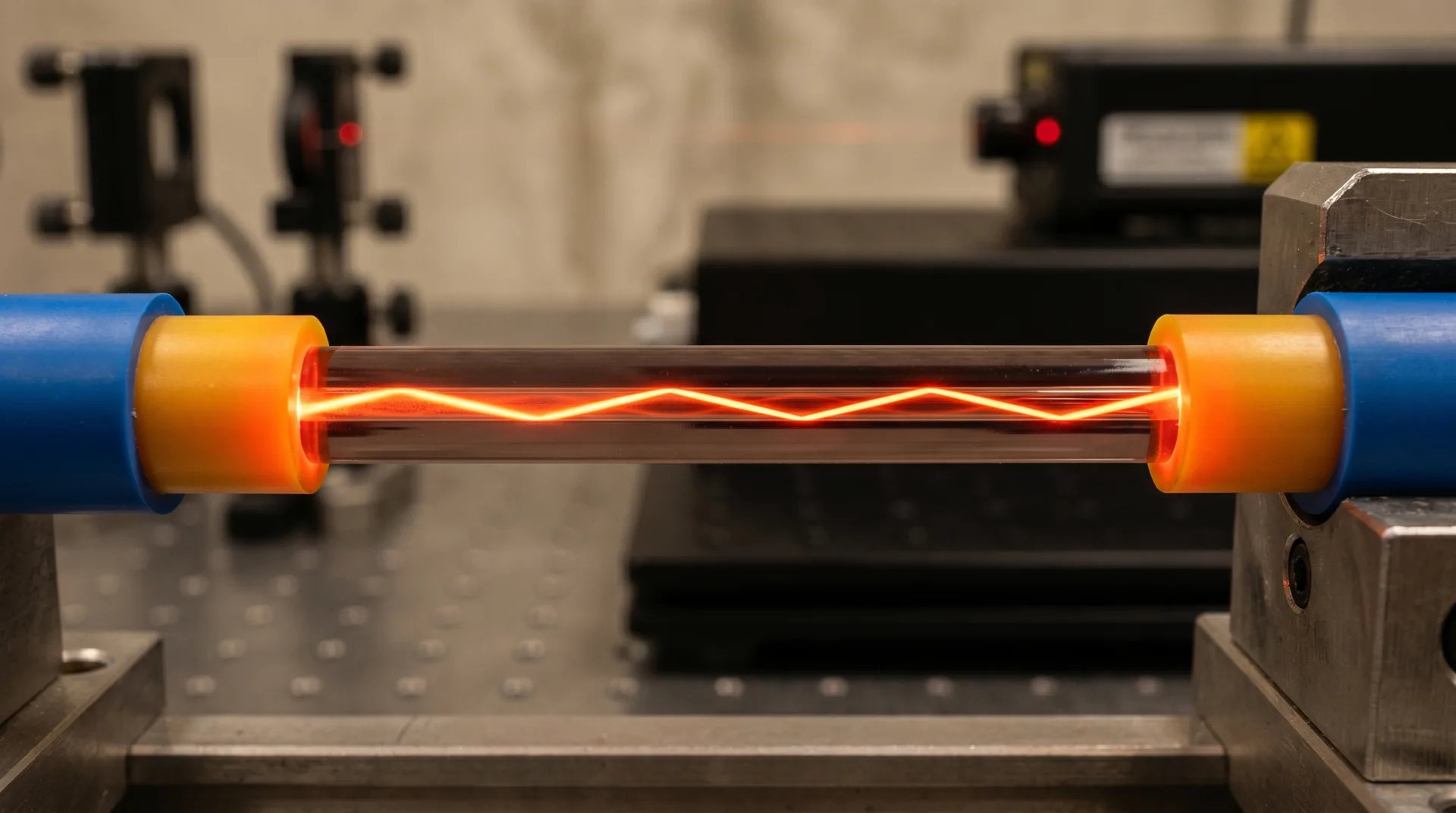
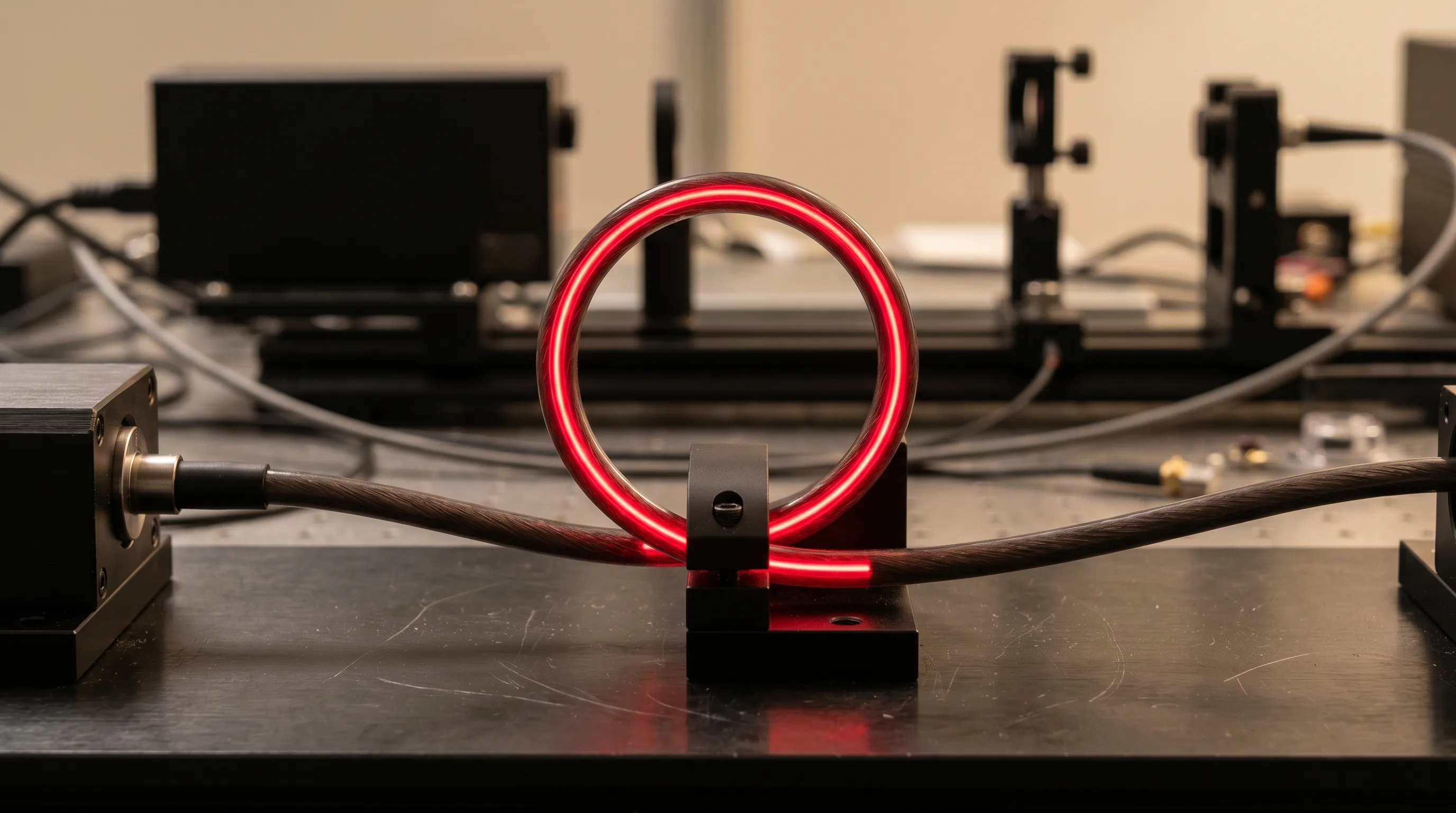
It’s far more than folklore—it’s waveguide physics in action. At the heart of every optical fiber lies a carefully engineered balance: the core’s higher refractive index traps light via total internal reflection, but only if the light strikes the core-cladding boundary at a shallow enough angle. Exceed that critical angle—by bending the fiber—and photons leak into the cladding, never to return.
Macrobending loss becomes significant when the bend radius falls below the manufacturer’s specification (typically 10–30 mm for single-mode fiber). What’s often overlooked is that loss is wavelength-dependent: a bend that’s tolerable at 1310 nm may cause >1 dB loss at 1625 nm—critical for OTDR monitoring or CWDM systems. In dense patch panels or cramped enclosures, this “invisible” loss accumulates silently, degrading link budgets without triggering alarms.
Even more insidious is microbending, caused by localized pressure from cable ties, crushed conduits, or thermal cycling in outdoor plant. These sub-millimeter deformations perturb the guided mode, scattering light and increasing attenuation. Unlike a clean break, microbending rarely shows up on visual inspection—but it erodes signal-to-noise ratio over time, especially in coherent 400G+ systems where every 0.1 dB matters.
The takeaway? Fiber isn’t just “flexible glass.” It’s a precision optical waveguide that demands respect for its geometric tolerances—bending isn’t a mechanical concern; it’s an optical one.
Isn't Modern Fiber So Pure That Impurities No Longer Matter?
Purity has improved dramatically—yet residual imperfections still define performance ceilings. Consider the hydroxyl (OH⁻) ion: a byproduct of moisture during manufacturing, it creates a notorious absorption peak near 1383 nm. While ITU-T G.652.D “low-water-peak” fiber has suppressed this to <0.31 dB/km, legacy G.652.B fiber can exhibit >1 dB/km loss in the same band—rendering the E-band (1360–1460 nm) unusable for CWDM.
But water isn’t the only ghost in the glass. Trace metals (iron, copper), oxygen deficiencies, or even isotopic variations in silica can introduce Rayleigh scattering, the fundamental loss floor of optical fiber (~0.12–0.15 dB/km at 1550 nm). This isn’t a defect—it’s a thermodynamic inevitability arising from frozen-in density fluctuations at the molecular scale. No amount of engineering can eliminate it; we can only design around it. For how manufacturers minimize these losses at the material level, see our explainer on the raw materials of high-quality optical fiber glass.
Moreover, refractive index profile deviations—even at the ±0.1% level—distort the mode field diameter (MFD). In single-mode fiber, MFD mismatch between spliced segments causes intrinsic splice loss, while in multimode fiber, core ellipticity or graded-index errors exacerbate differential mode delay (DMD), limiting bandwidth-distance products.
In short: fiber purity isn’t binary. It’s a spectrum of atomic-scale compromises that directly dictate how far, how fast, and how reliably light can travel.
Aren't Connectors Just Simple Interfaces? Why Do They Cause So Many Real-World Failures?
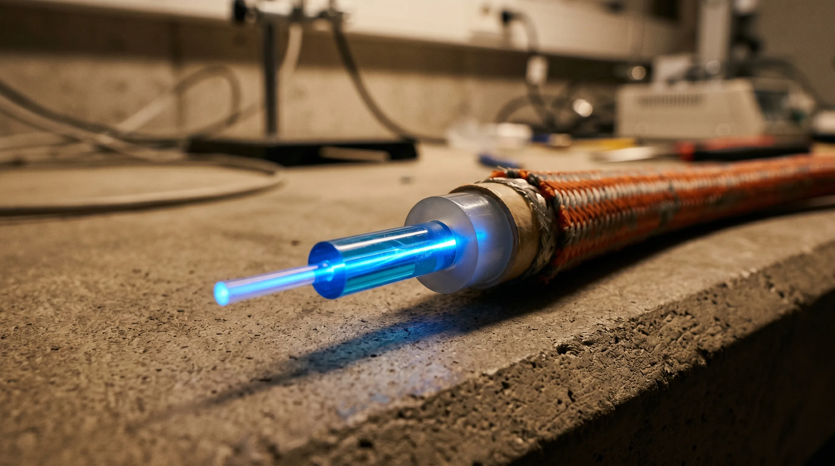
Because a connector isn’t just a plug—it’s a sub-micron optical alignment system operating in a world of dust, humidity, and human error. Consider this: the core of a single-mode fiber is just 9 microns wide—less than a tenth the width of a human hair. Aligning two such cores with <0.5 µm lateral offset, <0.5° angular tilt, and zero end-face contamination is an act of precision engineering. Selecting the right fiber optic connectors and inspecting every mating face is therefore non-negotiable in a production network.
Yet in the field, connectors face relentless challenges:
- Contamination: A 1-micron dust particle can block 10% of the core area, causing 0.5–1.0 dB loss and increased back reflection. Oils from skin create thin films that induce interference fringes (Fresnel reflections), destabilizing laser sources.
- Poor polish: Scratches, pits, or “comet tails” on the ferrule end-face scatter light and create localized hotspots that accelerate degradation under high power.
- Mating force inconsistencies: In multi-fiber MPO connectors, uneven spring pressure leads to non-uniform physical contact, causing channel-to-channel loss variation in parallel optics (e.g., 400G-SR8).
The data is stark: industry studies show >70% of fiber network faults originate at connection points. This isn’t a reflection of fiber’s weakness—it’s a testament to how unforgiving light is of imperfection. Hence the rise of inspection-before-mating protocols, automated cleaning tools, and IEC 61300-3-35 certification standards. In fiber optics, cleanliness isn’t optional—it’s optical hygiene.
Can Environmental Factors Like Temperature or Moisture Really Affect a Signal That's Just Light?
Yes—because while light doesn’t conduct electricity, the materials guiding it absolutely respond to the environment. For a focused treatment of the temperature angle, see our piece on whether temperature changes really impact fiber performance.
Take thermal effects: silica’s refractive index changes with temperature (~1×10⁻⁵/°C), and the fiber’s physical length expands (~0.55 ppm/°C). In uncontrolled environments—like aerial cables in desert climates—daily temperature swings of 60°C induce thermo-optic phase shifts that destabilize interferometric sensors or coherent transmission systems. More critically, differential expansion between the fiber, buffer tubes, and strength members can induce microbending loss if the cable design lacks proper strain relief.
Then there’s moisture and hydrogen. Water ingress—through jacket breaches or imperfect seals—leads to hydrogen generation via redox reactions with metal components. Hydrogen molecules diffuse into the glass lattice, forming Si–H and Ge–H bonds that absorb light across multiple bands (peaking near 1240, 1380, and 1600 nm). This hydrogen darkening is permanent and cumulative, particularly problematic in buried or submarine cables where replacement is prohibitively expensive.
Even radiation, while niche, matters in aerospace or nuclear applications. High-energy particles create color centers (defects) that absorb photons—a phenomenon quantified as radiation-induced attenuation (RIA). Mitigation requires specialty fibers doped with cerium or phosphorus to “trap” radiation damage before it affects transmission.
The lesson? Fiber may ignore electromagnetic chaos, but it lives in a physical world governed by chemistry, thermodynamics, and time.
In High-Speed or Long-Haul Systems, Can Light Actually Interfere With Itself?
Absolutely—and this is where fiber transitions from a passive pipe to an active nonlinear medium. At high optical powers (>0 dBm per channel) or over ultra-long distances (>1000 km), the intense electric field of the light modifies the fiber’s own refractive index, triggering a suite of nonlinear optical effects:
- Stimulated Brillouin Scattering (SBS): Photons interact with acoustic phonons, generating a backward-propagating Stokes wave. This not only drains forward power but can destabilize DFB lasers. SBS threshold is low (~5–7 dBm in standard SMF), so systems use dithering (frequency modulation) or broader linewidth lasers to raise it.
- Kerr nonlinearities: The intensity-dependent refractive index causes self-phase modulation (SPM) and cross-phase modulation (XPM), broadening pulses and inducing crosstalk in WDM systems. In dispersion-managed links, this interplay with chromatic dispersion creates complex signal distortions.
- Four-wave mixing (FWM): In low-dispersion fibers (e.g., NZDSF), three wavelengths can mix to generate a fourth—creating in-band interference that’s indistinguishable from real data. This is why modern submarine cables use large-effective-area fibers (LEAF) or hybrid dispersion maps to suppress FWM.
These aren’t failures—they’re fundamental limits that define the Shannon capacity of an optical channel. Overcoming them requires co-design of fiber, modulation format (e.g., QPSK, 16-QAM), and digital signal processing (DSP) in the receiver. In this regime, fiber isn’t just a medium—it’s part of the signal processing chain.
If Fiber Doesn't Radiate, Is It Automatically Secure Against Eavesdropping?
Not at all. Optical silence ≠ security. While fiber doesn’t leak electromagnetic signals, it can be compromised through physical-layer attacks:
- Bend-loss tapping: An attacker applies controlled stress to induce localized loss, then captures the leaked light with a high-sensitivity photodetector. Modern countermeasures include optical intrusion detection systems (OIDS) that monitor for anomalous loss via OTDR or pilot tones.
- Fused coupler taps: A short section of fiber is heated and stretched to fuse with a “victim” fiber, siphoning off 1–5% of the signal. This is nearly undetectable without baseline loss profiling.
- Laser-based side-channel attacks: By injecting a probe laser and analyzing backscatter from connectors or splices, attackers can infer data patterns—a technique demonstrated in lab settings against quantum key distribution systems.
True security requires defense in depth: physical conduit hardening, continuous optical monitoring, encryption at Layer 1 (e.g., MACsec or OTN encryption), and strict access controls. Fiber’s EMI immunity is a feature, not a fortress.
Does Fiber Really Last Decades Without Degradation — Or Is That Marketing Hype?
Fiber is remarkably stable, but longevity isn’t guaranteed—it’s engineered. Two key aging mechanisms threaten long-term reliability:
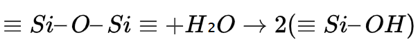
Static fatigue (stress corrosion cracking): In the presence of moisture, tensile stress at microscopic surface flaws causes slow crack growth via the reaction shown below. Over decades, this can reduce tensile strength by 30–50%, risking fracture during maintenance or seismic events. Hermetic carbon coatings mitigate this in harsh environments.
Hydrogen aging: As noted earlier, hydrogen diffusion causes permanent attenuation increase. Accelerated aging tests (e.g., 85°C/85% RH for 30 days) simulate 20+ years of field exposure. Fibers not qualified for such tests may degrade unexpectedly in humid climates.
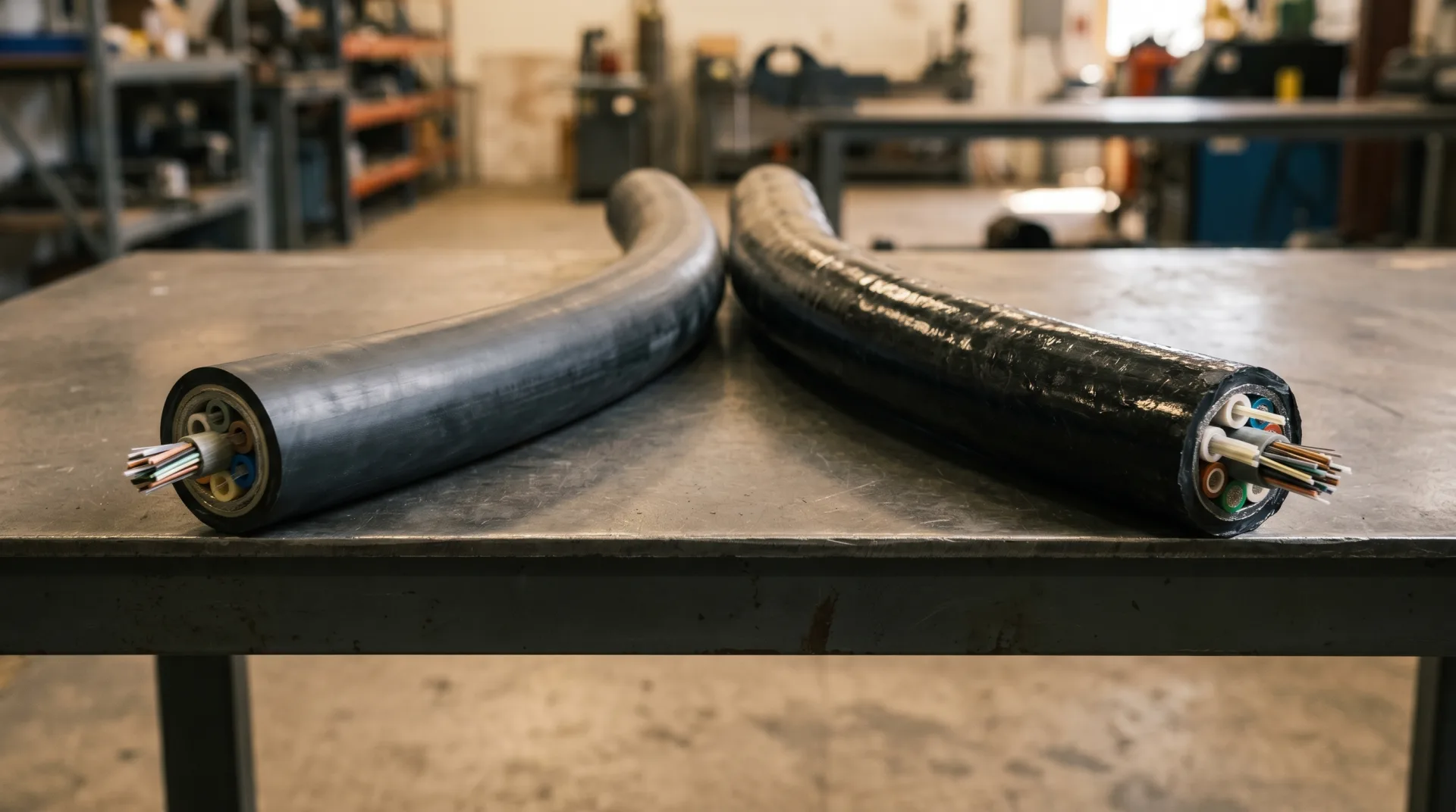
Moreover, coating degradation from UV exposure (in aerial cables) or chemical solvents can embrittle acrylate layers, reducing protection against microbending. Industry standards like Telcordia GR-20 define rigorous aging protocols—but not all “OSP-rated” cables meet them equally. Buried plant in particular calls for proper depth and duct design—see our guide on how deep should we bury fiber optic cable.
So yes, fiber can last 25+ years—but only if specified, installed, and protected with its full lifecycle in mind.
Could the Real Problem Lie Outside the Fiber — In Transceivers, Design, or Configuration?
Frequently. The fiber is just one link in a multi-domain optical chain. Common system-level pitfalls include:
- Modal bandwidth mismatch: Deploying OM4-optimized 100G-SR4 optics on legacy OM1 fiber causes severe modal dispersion—link failure is inevitable, even if the fiber passes Tier 1 certification.
- Dispersion budget errors: In 10G+ links over legacy fiber, unaccounted chromatic dispersion (>17 ps/nm·km in SMF at 1550 nm) smears pulses. Without proper compensation (DCF modules or coherent DSP), BER skyrockets.
- Optical return loss (ORL) issues: Poor connectors or open ports reflect light back into lasers, causing relative intensity noise (RIN) and wavelength instability—especially in analog RFoG or PON systems.
The best fiber plant can be undone by a misconfigured transceiver or an overlooked spec sheet. End-to-end validation—not just fiber testing—is non-negotiable in modern networks.
So… Is Fiber Truly Reliable, or Are We Just Lucky It Works So Well?
Fiber’s reliability isn’t luck—it’s the result of centuries of optics research, decades of materials science, and relentless field refinement. But it’s not magic. Its resilience stems from avoiding common failure modes (EMI, crosstalk), not from being universally invulnerable.
What makes fiber extraordinary is its asymmetry of failure: it fails quietly, predictably, and usually at human interfaces—not from cosmic rays or solar flares. This allows engineers to design robust, monitorable, and maintainable systems.
Yet that very predictability demands vigilance. As we push toward 800G, co-packaged optics, and hollow-core fibers, the margin for error shrinks. The engineers who succeed won’t be those who assume fiber is “just light in a tube,” but those who respect light as a physical phenomenon—elegant, powerful, and exquisitely sensitive to the world it traverses.
Final Thought: Are We Stewards of Light — or Just Its Couriers?
Perhaps the deepest truth about fiber optics isn’t technical—it’s philosophical. We don’t “send data through fiber.” We entrust light with our most critical conversations, transactions, and discoveries, and ask it to cross continents without faltering.
That trust is earned not by the fiber alone, but by the people who design, install, inspect, and maintain it. Every clean connector, every documented bend radius, every calibrated OTDR trace—is an act of stewardship.
So yes, the light signal can be disrupted. But with knowledge, discipline, and humility, we can ensure it rarely is. And in doing so, we don’t just build networks—we honor the physics that makes them possible. For the cable-design side of this story—how jacket construction resists these very stressors—see tight-buffered vs loose-tube fiber optic cables, or browse our range of outdoor fiber optic cable engineered for these environments.