How Much Loss Is Added When Using a Passive Splitter?
How much signal loss are you really adding when you insert a passive PLC splitter into a fiber link? Drawing from information commonly found in technical resources and product datasheets, this guide breaks down the mechanics, quantifies the loss for every common split ratio, explains why engineers and network designers care so much about this number, and presents it in a detailed, practical way that applies to real deployments.
The Unavoidable Tax: Signal Loss in Passive Splitters
You've got a signal — maybe it's lightning-fast data zipping down a fiber optic cable, a video stream heading to multiple screens, or an antenna feed for different TVs. You need to share it, to send that one input to several different places. The go-to solution is often a splitter. But if you opt for a passive splitter, you're about to pay a tax — a signal strength tax, measured in decibels.
Unlike their active cousins (which we discuss in active vs. passive splitter: what's the difference), passive splitters are fundamentally simple. They're like plumbing fixtures for signals, dividing the flow without adding any extra pressure or energy. This simplicity is a huge plus — they're reliable, don't need power, and are relatively inexpensive. But this simplicity comes at a cost: signal attenuation, or loss.
For anyone setting up a network, installing audio/video equipment, or dealing with signal distribution in any form, understanding this loss isn't just technical trivia. It's a critical factor that directly impacts whether your signal reaches its destination strong enough to be usable. Too much loss, and you're looking at slow speeds, poor quality, intermittent connections, or even total signal failure. This is what users genuinely care about — the practical outcome of that seemingly abstract dB number.
So, let's peel back the layers and find out exactly how much loss a passive splitter adds, why it does it, and what that means for you.
Why Passive Splitters Cause Loss
Imagine you have a single pipe delivering water, and you use a simple "Y" junction to split it into two pipes. Assuming equal flow resistance, the water flow rate (or pressure, in a simplified analogy) into each of the two smaller pipes will be less than the flow rate in the original pipe. You haven't added any water; you've just divided the existing supply.
Passive splitters work on the same principle. Whether they're dividing electrical energy (in older electrical splitters) or light energy (in modern fiber optic splitters), they are simply taking the total energy of the incoming signal and distributing that same total energy among the output paths. The energy doesn't magically increase or get regenerated.
Since the energy is shared, the signal strength (which is related to energy or power) at each individual output port is necessarily weaker than the signal strength at the input port. This reduction in signal strength is what we call attenuation, and it's the inherent "loss" introduced by the passive splitting process. No matter how well a passive splitter is manufactured, this fundamental energy conservation principle cannot be escaped — you are always distributing a fixed amount of energy, never creating new signal power.
Understanding Decibels (dB) and Why They Matter
Signal loss (and gain) in telecommunications and electronics is measured using the decibel (dB) scale. The dB scale is logarithmic, which makes it very convenient for representing large ratios of power and for adding up losses (and gains) linearly along a signal path. (For a deeper look at what constitutes acceptable dB loss in a fiber link, see what is a good dB loss for fiber optics.)
- A positive dB value usually indicates a gain (like amplification).
- A negative dB value or simply stating a "loss of X dB" indicates attenuation.
Crucially, when you have multiple components in a signal path, you add their dB losses (and subtract any dB gains) to find the total loss. This additive property is why the dB scale is so useful for calculating total signal budgets or link budgets. For example, if a 1×8 splitter adds 9.73 dB and 2 km of single-mode fiber adds 0.6 dB, the combined loss from just those two elements is already 10.33 dB — before you've counted a single connector.
How Much Loss, Exactly?
The total loss added by a passive splitter isn't just one number. It's primarily composed of two distinct parts: the unavoidable split ratio loss and the excess insertion loss from the device's physical construction.
Part 1: Split Ratio Loss (Theoretical Loss)
This is the unavoidable loss that results purely from dividing the signal energy equally among the output ports. It's based on the logarithm of the number of ways the signal is split. For a splitter with N output ports (a 1×N splitter), the theoretical loss per output port is approximately:
Loss (dB) = 10 × log10(N)
The table below shows typical theoretical losses for common split ratios:
| Splitter Type | Output Ports (N) | Theoretical Loss per Port |
|---|---|---|
| 1×2 | 2 | ≈ 3.01 dB |
| 1×4 | 4 | ≈ 6.02 dB |
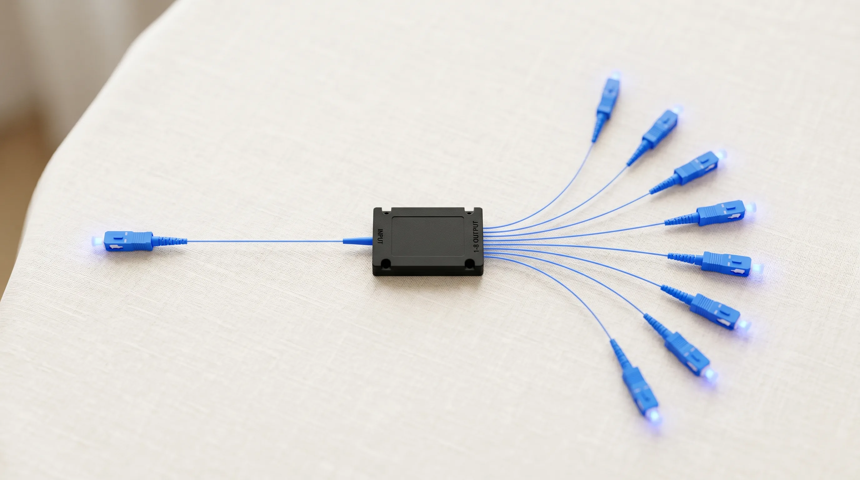
| 1×8 | 8 | ≈ 9.03 dB |
| 1×16 | 16 | ≈ 12.04 dB |
| 1×32 | 32 | ≈ 15.05 dB |
| 1×64 | 64 | ≈ 18.06 dB |
What this means in plain English: every time you double the number of splits, you add roughly another 3 dB of loss to each output port. A 3 dB loss means the signal power is halved. So, at a 1×4 split (two doublings), each output has roughly 1/4 the power (−6 dB). At a 1×8 split, it's 1/8 the power (−9 dB), and so on. This loss applies to every signal going through the splitter, at every output port.
Part 2: Insertion Loss (Practical Loss)
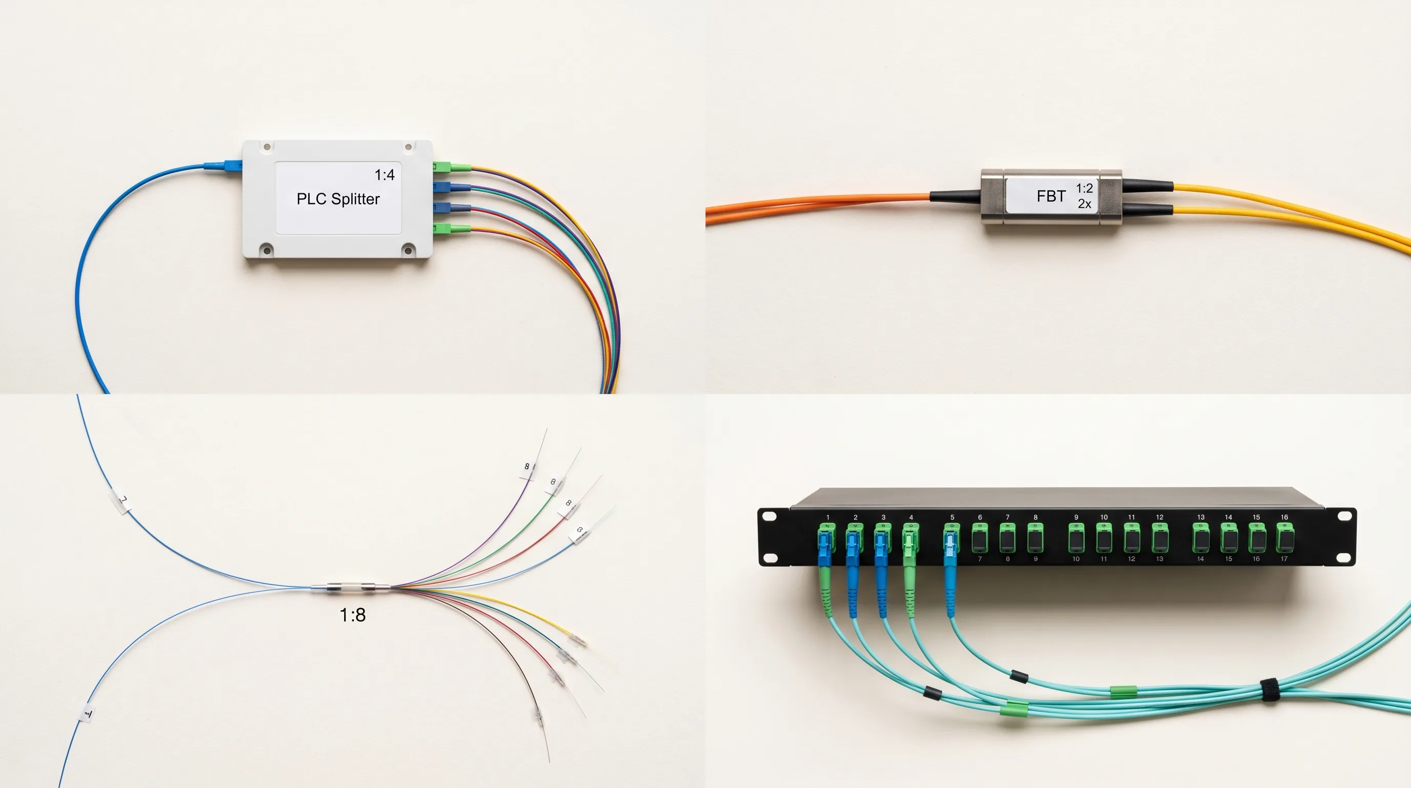
Insertion loss is the additional, non-ideal loss introduced by the physical construction of the splitter itself. It accounts for imperfections in how the signal is coupled or divided, material absorption, scattering, reflections, and so on. Insertion loss varies depending on the quality of the splitter, the type of splitter technology (e.g., FBT vs. PLC in fiber), the manufacturing precision, and even the specific split ratio.
Insertion loss is added on top of the theoretical split ratio loss. A high-quality fiber optic PLC splitter will typically show the following excess insertion loss figures:
| Splitter Type | Typical Excess Insertion Loss |
|---|---|
| 1×2 | ~0.1 dB |
| 1×4 | ~0.3–0.5 dB |
| 1×8 | ~0.5–0.8 dB |
| 1×16 | ~0.8–1.2 dB |
| 1×32 | ~1.0–1.5 dB |
| 1×64 | ~1.5–2.0 dB |
Calculating Total Splitter Loss per Port
The actual, measurable loss you experience when using a passive splitter (at any given output port) is the sum of the theoretical split ratio loss and the insertion loss for that specific splitter:
Total Splitter Loss (dB) per Output Port = Theoretical Split Ratio Loss (dB) + Insertion Loss (dB)
Examples using typical numbers:
| Splitter Type | Theoretical Loss | Typical Insertion Loss | Total Loss per Port |
|---|---|---|---|
| 1×2 | ~3.01 dB | ~0.1 dB | ~3.11 dB |
| 1×8 | ~9.03 dB | ~0.7 dB | ~9.73 dB |
| 1×32 | ~15.05 dB | ~1.2 dB | ~16.25 dB |
This "Total Splitter Loss" is the number you'll typically see listed on a product datasheet for a specific passive splitter, sometimes just called "Insertion Loss" but actually representing the sum of splitting and manufacturing losses. When comparing splitters from different vendors, pay close attention to whether the datasheet is quoting only the excess insertion loss or the full per-port loss including the split ratio contribution — the two numbers look very different, and confusing them is a common design mistake.
What's the Total Link Loss?
It's crucial to remember that the loss added by the passive splitter is not the only loss in your signal path. Your total signal loss from the source (transmitter) to the destination (receiver) will be the sum of all components in the link. The splitter loss is often the single largest contributor in a well-designed short-to-medium-distance network, but cable attenuation, connector loss, and splice loss all add up and must be accounted for in any serious link budget calculation.
Total Link Loss (dB) = Loss at Splitter 1 + Loss at Splitter 2 (if any) + Cable/Fiber Loss + Connector Losses + Splice Losses + Any Other Component Losses
- Cable/Fiber Loss: signal weakens as it travels along the cable or fiber. This is specified in dB per unit length (e.g., dB/km for fiber, dB/100 ft for coax). Longer runs mean more loss.
- Connector Loss: every time you use a connector pair (connecting two cables, or a cable to equipment), there's a small loss — typically 0.2 dB to 0.5 dB per connection pair in fiber optics, varying based on connector type, cleanliness, and quality.
- Splice Loss: when joining cables permanently (especially fiber), fusion or mechanical splices also introduce a small loss — typically lower than connector loss (e.g., 0.05 dB for a good fusion splice).
Why Do Users Care So Much About This Loss Number?
Understanding the passive splitter's loss isn't just an academic exercise; it has direct, practical consequences that users and network operators care deeply about. Here are the six most important reasons why the dB loss figure on a splitter datasheet matters in practice:
- Link budget consumption. Every dB of loss eats into the total "loss budget" of the system — the maximum signal weakening that can occur before the receiver can no longer reliably detect the signal. A significant loss from a passive splitter reduces how far the signal can travel after the splitter, or limits how many other lossy components (like connectors) can be in the path.
- Equipment cost. If the total loss is high, the receiving equipment must be more sensitive (able to detect weaker signals). More sensitive equipment can be more expensive.
- Data rate and signal quality. For digital signals (like internet data), excessive loss doesn't just make the signal weaker; it makes it harder for the receiver to distinguish 1s from 0s. This leads to increased error rates, requiring retransmission, which slows effective speed. For analog signals (like older video), loss leads to a snowy, distorted, or weak picture.
- Reliability margins. A signal close to the minimum sensitivity threshold is vulnerable to noise, environmental changes (temperature affecting component performance), or small additional losses over time (dirty connectors). This can lead to intermittent connections that are frustratingly difficult to diagnose.
- Network planning and design. Professionals designing networks — especially fiber optic ones like FTTH — must meticulously calculate the total link budget, taking into account every dB of loss from splitters, cables, and connections. Miscalculating or underestimating passive splitter loss is a common pitfall that leads to costly rework.
- Troubleshooting. When a signal isn't working, understanding expected loss values helps pinpoint the problem. If the measured loss through a splitter is significantly higher than the datasheet specifies, it indicates a faulty component or dirty connection at the splitter.
How to Manage Passive Splitter Loss
Since passive splitter loss is unavoidable, managing it effectively is key to a successful design. If initial design calculations show the total link loss is too high when using a passive splitter — meaning it exceeds the optical power budget of your transceivers — you have a few options short of switching to an active system entirely:
- Use splitters with fewer outputs (e.g., two 1×4 splitters instead of one 1×8, if topology allows — although this may increase connection loss elsewhere).
- Reduce the largest contributor to loss besides the splitter (e.g., shorten cable runs, clean connectors).
- Invest in high-quality PLC splitters with lower excess insertion loss, cleaner factory-installed connectors, and lower-loss fiber or cable.
- If the passive approach simply doesn't work for the required distances or split counts while staying within the loss budget, an alternative approach involving active components (amplifiers, regenerators, active splitters/switches) may be necessary.
The Passive Splitter's Trade-off
Passive splitters offer compelling advantages in terms of simplicity, reliability, and cost, making them ideal for many signal distribution applications — perhaps most notably in the large-scale deployments of Fiber to the Home (FTTH) networks, where a single central office fiber may serve dozens or even hundreds of subscribers through a cascaded splitting architecture. However, their fundamental design dictates an unavoidable signal tax — attenuation or loss — which is primarily a function of the split ratio but also includes excess insertion loss from the component's manufacturing process and material quality.
This loss, measured in decibels, is not just a technical specification; it's a critical factor that directly impacts signal reach, performance, reliability, and the overall viability of the network design. Understanding the inherent loss of a passive splitter, how to quantify it, and how it contributes to the total signal loss in a system is essential for successful implementation and troubleshooting. For more on what causes the majority of loss in fiber optics, or to explore the types of optical fiber splitters available for your network, visit the linked cluster articles.
While passive splitters bring simplicity and robustness, managing their unavoidable signal attenuation is key to ensuring the signal successfully completes its journey from source to all destinations. Users and network designers who understand this loss — how to calculate it, how it accumulates with cable and connector losses, and how to budget for it — are in a far better position to build reliable, cost-effective fiber networks that work as advertised from day one.