Low-Loss Optical Fiber: From Raw Materials to Final Product
What's the Science Behind Low-Loss Optical Fiber—From Raw Materials to Final Product?
At first glance, optical fiber seems deceptively simple: a strand of ultra-clear glass that guides light across oceans. But behind that elegance lies one of the most sophisticated feats of modern materials science — a journey that begins with common sand and ends in a product so pure, so precisely structured, and so optically refined that it approaches the theoretical limits of physics.
So how do we turn raw silica into a medium where light can travel 100 kilometers with less loss than it would suffer passing through a windowpane? What scientific principles, manufacturing breakthroughs, and quality controls make today's low-loss fiber possible?
Let's trace the full arc — from quartz grains to coherent terabit streams — with the depth this invisible infrastructure deserves.
Can You Really Make "Perfect" Glass from Sand?
In a word: yes — but only if you redefine "sand." The starting point isn't beach sand (riddled with iron, calcium, and organic impurities), but high-purity synthetic silica. Two primary methods dominate:
1. Modified Chemical Vapor Deposition (MCVD)
Developed at Bell Labs in the 1970s, MCVD remains the gold standard for telecom fiber. Here's how it works:
- A rotating pure silica tube (the future cladding) is heated by a traversing oxy-hydrogen torch (about 1,600 °C).
- Precursor gases — silicon tetrachloride (SiCl₄) for silica, germanium tetrachloride (GeCl₄) for core doping, and oxygen — are injected inside the tube.
- At high temperature, they react: SiCl₄ + O₂ → SiO₂ + 2Cl₂ and GeCl₄ + O₂ → GeO₂ + 2Cl₂.
- The resulting soot particles deposit on the inner wall, then sinter into a thin, doped glass layer. By varying GeO₂ concentration, engineers build a graded or step-index core with nanometer-scale precision.
Once deposition is complete, the tube is collapsed into a solid preform — a 1–2 meter rod that contains the entire refractive index profile of the future fiber, scaled up about 100 times.
2. Outside Vapor Deposition (OVD) & Vapor Axial Deposition (VAD)
Used by Corning and others for high-volume production, these methods build the preform layer-by-layer from the outside in (OVD) or axially upward (VAD). Soot is deposited on a rotating bait rod or seed, then sintered in a furnace to form a porous preform, which is later dehydrated and vitrified.
Why go through all this? Because impurities at the parts-per-billion (ppb) level determine optical loss. Iron, copper, or OH⁻ ions absorb light; bubbles or density fluctuations scatter it. Synthetic processes eliminate these far more effectively than melting natural quartz ever could.
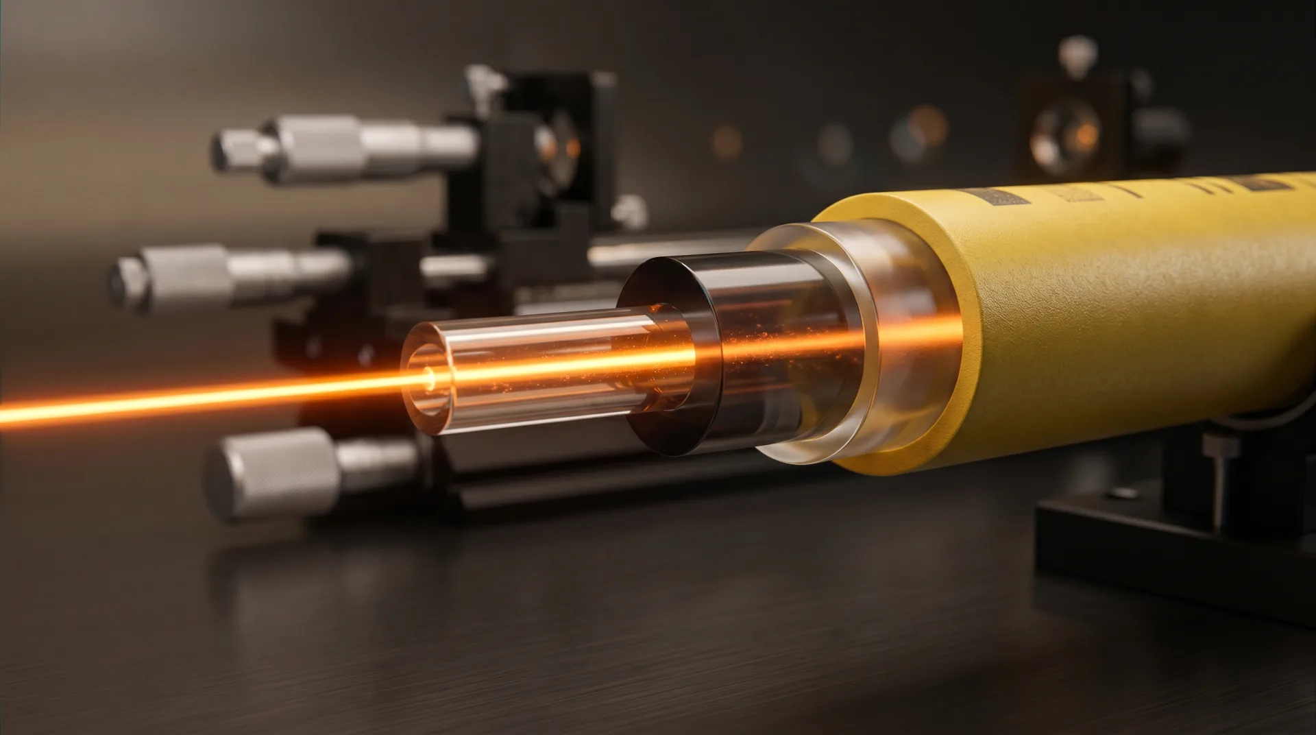
What Makes Light "Stay" in the Core — and Travel So Far Without Fading?
Two foundational principles govern low-loss propagation:
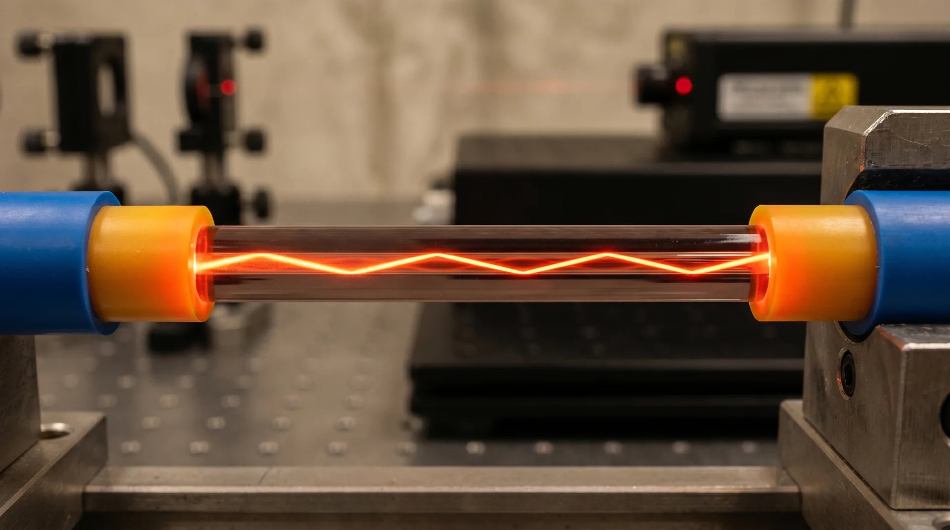
1. Total Internal Reflection (TIR)
The core is doped with germania (GeO₂), which slightly increases its refractive index (about 1.468 vs. 1.457 for pure silica cladding). When light hits the core-cladding boundary at a shallow angle, it reflects entirely back into the core — like a mirror made of physics, not metal.
But TIR alone isn't enough. Without extreme material purity, light would still be absorbed or scattered.
2. Minimizing Fundamental Loss Mechanisms
Even in perfect glass, light doesn't travel forever. Three physical phenomena set the theoretical loss floor:
- Rayleigh scattering: Caused by frozen-in density fluctuations from the molten state. It scales as 1/λ⁴ — which is why loss is lower at 1,550 nm (0.2 dB/km) than at 850 nm (2.5 dB/km). This is unavoidable — a thermodynamic limit of amorphous materials.
- Infrared absorption: Beyond 1,600 nm, molecular vibrations in silica absorb photons. This defines the long-wavelength edge of the telecom window.
- Ultraviolet absorption: Below 800 nm, electronic transitions absorb light — setting the short-wavelength limit.
The lowest theoretical loss for silica fiber occurs at 1,550 nm: about 0.14 dB/km. Modern fibers achieve 0.15–0.17 dB/km — remarkably close to this limit. For a practical breakdown of what constitutes acceptable loss in deployed links, see our guide on what is a good dB loss for fiber optics.
How Do You Eliminate the "Water Peak" That Once Blocked an Entire Band?
For decades, a spike in attenuation near 1,383 nm — the "water peak" — rendered the E-band unusable. It came from hydroxyl (OH⁻) ions, introduced as water vapor during manufacturing.
The breakthrough came with dehydration chemistry:
- During preform sintering, chlorine gas (Cl₂) or dry oxygen is flowed through the porous soot.
- It reacts with OH⁻ groups: Si–OH + Cl₂ → Si–Cl + HOCl (gas).
- The volatile byproducts are purged, reducing OH⁻ to less than 1 ppb.
The result? ITU-T G.652.D "low-water-peak" fiber, which opens the full 1,260–1,625 nm spectrum for CWDM, PON, and 5G fronthaul. This wasn't just an improvement — it doubled usable bandwidth without laying new cable.
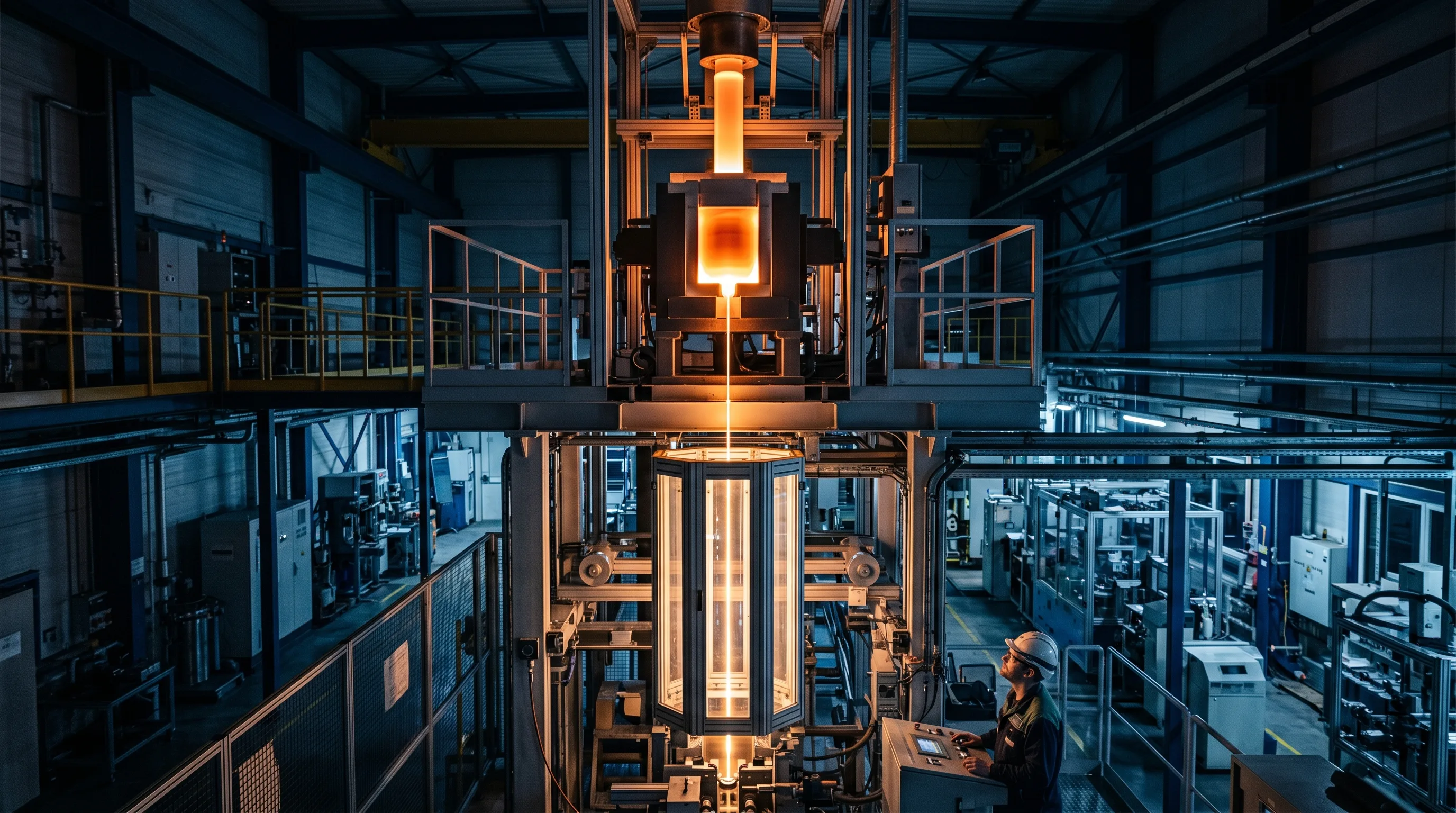
How Is the Preform Turned Into Kilometers of Fiber — Without Introducing Defects?
In the drawing tower, science meets high-speed precision:
- The preform is fed into a graphite or zirconia furnace at about 2,000 °C.
- The tip melts, and a seed fiber is pulled downward by a capstan at 10–50 m/s.
- Diameter is monitored in real time by a laser micrometer; feedback controls capstan speed to hold 125.0 ± 0.7 µm — critical for low splice loss.
- Immediately after drawing, the fiber is coated with dual-layer UV-cured acrylate: a soft inner layer that cushions microbending, and a hard outer layer that provides mechanical protection.
- It's spooled at high tension, with continuous monitoring for tensile strength, geometry, and coating concentricity.
One preform (about 10 kg) yields over 200 kilometers of fiber. Throughout, the environment is an ISO Class 5 cleanroom — because a single dust particle can cause a weak point or scatter center.
How Do You Verify That the Fiber Meets the Promise of "Low Loss"?
Rigorous, multi-stage testing ensures every kilometer performs:
- Attenuation vs. Wavelength: Measured via cut-back method per IEC 60793-1-40. Confirms loss at 1,310, 1,383, 1,550, and 1,625 nm.
- Mode Field Diameter (MFD): Critical for splice compatibility; measured interferometrically.
- Chromatic Dispersion: Verified to ensure pulse spreading stays within design limits.
- Proof Testing: Every fiber is tensile-tested to 100 kpsi (0.7 GPa) — simulating decades of installation stress.
- Geometric Uniformity: Core/cladding concentricity less than 0.5 µm prevents misalignment loss in mass splicing.
Only after passing these — and more — does fiber ship as G.652.D, G.654.E (for submarine), or G.655 (non-zero dispersion). This manufacturing discipline is why outdoor fiber optic cables built on these fibers can span tens of kilometers in harsh field conditions with minimal signal degradation.
What's Next? Are We Hitting the Limits of Silica?
We're approaching them — but not surrendering. Three frontiers are emerging:
1. Hollow-Core Fibers
Instead of guiding light through glass, these use photonic bandgap structures to confine light in air. Losses have dropped below 0.2 dB/km, with potential for 10 times lower latency and nonlinearity. Still expensive, but promising for quantum and high-frequency trading.
2. Multi-Core and Few-Mode Fibers
To overcome the "capacity crunch," fibers now pack 4–19 parallel cores or use spatial modes in a single core — multiplying data without new ducts.
3. Advanced Dopants and Purity
Ceria-doped fibers resist radiation; fluorine-doped claddings enable larger mode areas. And purification techniques now target parts-per-trillion impurity levels.
Yet for most applications, conventional silica remains unbeaten: cost-effective, reliable, and astonishingly close to nature's limits. Understanding what causes the majority of loss in fiber optics helps network engineers make informed choices about which fiber grade is right for their deployment.
Why Does This Invisible Thread Matter?
Because low-loss fiber isn't just infrastructure — it's civilization's nervous system. Every video call, medical scan, financial transaction, and climate model rides on photons that crossed continents with less loss than they'd suffer in your eyeglasses.
And that miracle isn't accidental. It's the result of decades of chemistry, physics, and relentless refinement — where scientists didn't just ask, "Can we guide light?" but "How perfectly can we do it?"
From sand to signal, the journey of optical fiber is a testament to human ingenuity: quiet, precise, and profoundly enabling. We may never see it — but we live inside its light. To learn more about how TTI Fiber brings this precision manufacturing to product form, visit our About Us page.